Cold Storage Engineering · Practical How-To Guide
How to Build a −25°C Freezer Room: A Step-by-Step Guide for a 3 m × 4 m × 2.5 m Cold Storage Room
This guide walks through the full engineering path for a small walk-in freezer in Xi'an, China — from cooling-load calculation and compressor selection to panels, valves, controls, refrigerant and commissioning. Every figure below follows one worked example: a 30 m³ room held at −25°C for storing already-frozen goods.
3.0 × 4.0 × 2.5 m · 30 m³ · −25°C · R404A · 2.5 HP low-temp unit · DJ-2.5/15 evaporator
Project Brief
1. What we are building — and the assumptions behind it
Before choosing any equipment, the engineer must fix the project definition. A freezer designed for storage of frozen goods is very different from a room that must freeze fresh product inside it; confusing the two is the most common sizing mistake.
| Internal size | 3.0 × 4.0 × 2.5 m |
|---|---|
| Volume | 30.0 m³ |
| Room temperature | −25°C |
| Refrigerant | R404A |
This worked example assumes the following conditions. If any of them differs on site, the load calculation and equipment selection must be repeated.
- Purpose: storage only. The room holds product already frozen to a core temperature of −18°C or below; it does not perform the freezing process itself.
- Location: the room sits inside a ventilated workshop, out of direct sun. The condensing unit is also sheltered and well aired.
- Goods flow: about 5% of room volume enters per day, at frozen temperature; normal, not heavy, door-opening frequency.
- Power supply: 380 V, three-phase, 50 Hz. A 220 V single-phase site would require a different single-phase low-temperature unit.
- Climate: a northern Chinese city (Xi'an / Zhengzhou type). Summer outdoor design dry-bulb around 35°C; the workshop air around 32°C.
If the room must freeze fresh or warm product to −25°C inside itself, this scheme no longer applies. That is a freezing tunnel / blast freezer duty: the latent heat of freezing multiplies the cooling load several times over, and the compressor, evaporator and defrost system must be sized from scratch using freezing-time calculations.
Step 1 · Cooling Load
2. Size the cooling load before picking a compressor
The cooling load is the total heat that must be removed from the room every hour to hold −25°C. Chinese cold-storage design standard GB 50072-2021 breaks it into four components: heat leaking through the insulated envelope, heat from the goods, heat released by the evaporator fan motors, and heat from people, lighting and door openings.
Design working conditions
The evaporator does not run at room temperature — it must be colder than the air it cools. With a 6 K temperature difference between room air and evaporating refrigerant:
- Evaporating temperature Te = −25 − 6 = −31°C
- Condensing temperature Tc ≈ 35 + 12 = 47.2°C (air-cooled condenser, 12 K rise above summer dry-bulb)
The four heat loads in this room
| Component | Heat load | How it is estimated |
|---|---|---|
| Q1 — Envelope transmission (walls, ceiling, floor) | 521.9 W | 150 mm PU panels, λ = 0.024 W/(m·K); walls 35 m², ceiling 12 m², floor 12 m², multiplied by each surface temperature difference. |
| Q2 — Goods heat | 30.1 W | About 240 kg/day of already-frozen product cooling from −18°C to −25°C, spread over 24 h; sensible heat only, latent heat absent. |
| Q3 — Evaporator fan motors | 270 W | Three 90 W fan motors on the DJ-2.5/15; motor heat dissipates straight into the room air. |
| Q4 — Operation (people, lighting, door infiltration) | 200 W | Intermittent staff, interior lighting and warm-air ingress through normal door openings, estimated for a small room in regular use. |
Adding the four components gives the cooling-equipment load Qe ≈ 1,022 W (1.02 kW). Piping losses and a safety margin are then applied: a 15% margin gives 1,175 W, and a conservative 25% margin gives Qm ≈ 1,277 W (1.28 kW). This 1.28 kW at the −31°C / 47°C working condition is the figure the compressor must deliver — not a nominal room-volume rule of thumb.
Why not use a simple "watts per cubic metre" shortcut? Online tables quoting 150–200 W/m³ for freezer rooms bundle freezing duty, frequent door openings, fast initial pull-down and a large margin into one coarse number. For a small storage-only room of already-frozen goods, a component-by-component calculation gives a lower, honest result; the shortcut would oversize the machine and waste energy.
Step 2 · Condensing Unit
3. Select the condensing unit (compressor + condenser)
The condensing unit sits outside the room and carries the high-pressure side of the cycle: compressor, air-cooled condenser, fan, receiver and frame. For this room it must deliver at least 1.28 kW of cooling at −31°C evaporating and 47°C condensing on R404A.
| Unit size | 2.5 HP low-temperature air-cooled condensing unit (market trade name: a "3 HP low-temperature" class machine); R404A; 380 V / 3 Ph / 50 Hz. |
|---|---|
| Required capacity | ≥ 1.8 kW at Te −31°C / Tc 47°C — about 40% headroom over the 1.28 kW conservative mechanical load. |
| Compressor type | Low-temperature liquid-injection or vapor-injection scroll of the ZF08KQE class (Copeland-style), or an equivalent semi-hermetic low-temperature piston compressor. |
| Accessories | Oil separator matched to displacement; optional suction accumulator to protect against liquid slugging on long suction lines or defrost liquid return. |
Do not fit a standard medium-temperature scroll here. Ordinary ZB-class scroll compressors are rated for evaporating temperatures roughly above −20°C. At −31°C the discharge temperature, oil condition and compression ratio go outside their safe range. A true low-temperature ZF/ZFI series — or a low-temp semi-hermetic piston machine — is required. Falling evaporating temperature also cuts capacity: roughly every 5°C lower evaporating temperature costs about 15% of the unit's rated cooling capacity, which is why catalog capacity must be checked at the −31°C / 47°C crossover point, not at a headline horsepower rating.
Step 3 · Evaporator
4. Choose the ceiling evaporator (air cooler)
The evaporator sits inside the room, mounted to the ceiling. It absorbs heat from the air blown across its finned coil. For a −25°C room the coil operates near −31°C, so frost forms quickly and fin spacing matters: narrow fins clog with ice, wide fins keep airflow stable between defrosts.
| Model | DJ-2.5/15 low-temperature ceiling air cooler. |
|---|---|
| Coil capacity | Nominal 2.49 kW at Δt = 7°C; heat-transfer area 15 m². |
| Fin spacing | 9 mm — the wide fin pitch required for sub-zero duty. |
| Fan circuit | 3 × 90 W motors, airflow 5,100 m³/h; 220 V. |
| Defrost | Electric defrost heater, 3.6 kW total, timed and temperature-controlled from the main panel. |
| Spare fittings | Hanging rods, leveling nuts, mushroom anchors, drain connection, seal strip, condensate drain pan. |
Why DJ and not DD or DL? DD and DL series air coolers use closely spaced fins for chilled and medium-temperature rooms (0°C to +10°C). At −25°C their coils frost into a solid block within a short defrost cycle, airflow collapses and the room cannot pull down. The DJ series with 9 mm fin pitch is the correct low-temperature family. In a tighter space a smaller DJ-1.8/12 (1.83 kW, 12 m², 2 × 90 W, 3,400 m³/h) can substitute after re-checking the load.
Step 4 · Insulated Shell
5. Build the insulated room shell
The refrigeration machine only removes heat that reaches the coil; the panel envelope stops heat entering in the first place. For a −25°C room the shell must be a continuous thermal barrier with no cold bridges at corners, joints, door frame or floor.
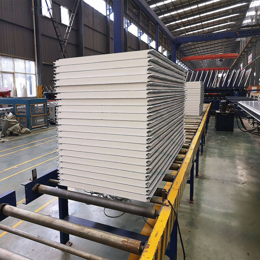
Shell components for this room
- Insulated panels: 150 mm double-color-steel PU / PIR panels, foam density 40 ± 2 kg/m³, λ ≤ 0.024 W/(m·K); wall, ceiling and floor panels, about 59 m² of panel area in total. Sun-exposed or conservative projects thicken the panels to 180 mm.
- Door: one single-leaf half-buried hinged door (or sliding door for goods traffic), opening about 900 × 1,900 mm. It carries a door-frame heater and observation-window heater, EPDM seals, an inside-opening escape latch and a viewing window.
- Floor: 150 mm floor insulation under a reinforced-concrete wearing slab. At −25°C the ground below cannot sit directly against uninsulated concrete: a ventilated air gap or floor heating wires protect against frost heave.
- Pressure relief port: a panel-mounted pressure equalization port balances inside and outside pressure so the door opens easily and panel joints do not leak as temperature swings.
- Fasteners and seals: hangers, angle aluminum, silicone sealant, self-tapping screws and connectors, included in the panel package.
On-site panel assembly runs ceiling panels first, then walls and floor; corner joints are sealed, and evaporator hangers are embedded while the ceiling is being laid.
Step 5 · Valves, Piping & Insulation
6. Lay out the valves, copper piping and insulation
Between the condensing unit and the evaporator runs the refrigerant circuit: a liquid line carrying condensed refrigerant, and a suction line returning cold vapor to the compressor. Valves in this circuit meter the refrigerant, shut off flow on stop, remove moisture and protect the compressor.
Valve and protection package
| Item | Reference spec | Purpose |
|---|---|---|
| Thermostatic expansion valve | TES5 / TE5, external equalizer, R404A; orifice sized for 1.3–1.8 kW | Meters liquid refrigerant into the evaporator; external equalizing line tied after the bulb. |
| Solenoid valve | EVR6, φ12 mm, R404A, 220 V coil | Closes the liquid feed when the compressor stops, preventing flood-back. |
| Filter drier | DML053 / DCL053, φ12 mm, molecular sieve, R404A | Traps moisture and acid; replaced after any open-system service. |
| Sight glass | SG, φ12 mm, with humidity indicator | Shows liquid condition, bubbles and refrigerant moisture color. |
| Service valves | Suction φ19 mm, discharge φ16 mm, liquid φ12 mm | Isolate the compressor and circuit components for maintenance. |
| High/low pressure control | KP15; high cut-out 2.6–2.8 MPa, low cut-out 0.05–0.1 MPa, R404A | Shuts the compressor on unsafe pressures and feeds back to the control panel. |
| Pressure gauges | One high-side and one low-side gauge, R404A scale | On-site monitoring and commissioning adjustment. |
Piping sizes and insulation
| Line | Copper tube | Reference length |
|---|---|---|
| Suction line (cold vapor) | φ19 × 1.0 mm seamless copper | 8–10 m |
| Discharge line (hot gas) | φ16 × 1.0 mm seamless copper | 6–8 m |
| Liquid line | φ12 × 1.0 mm seamless copper | 8–10 m |
Suction and liquid lines are wrapped in B1 closed-cell rubber insulation at least 25 mm thick, with elbows, tees, joint sleeves, binding tape and sealant included; insulation must be continuous with no cold bridge. The internal drain line carries an electric heating cable and a U-shaped water seal, and slopes out of the room so meltwater cannot freeze and block the drain.
Step 6 · Controls & Heating
7. Wire the controls, door heaters and lighting
A low-temperature room is controlled by a dedicated cold-room electrical panel: it reads room temperature, starts and stops the compressor, schedules defrost, runs the fans, and trips out on high pressure, low pressure, phase loss, overload or alarm conditions. The panel also powers the anti-frost heaters that a −25°C room cannot do without.
- Control panel: Elitech ECB-5060 (or equivalent New Asia / Sanhe panel). Room thermostat, defrost by timer plus temperature cutoff, fan and condenser-fan control, high/low pressure protection, phase sequence and loss-of-phase protection, compressor overload, alarm output terminals; optional remote monitoring module.
- Interior lighting: two IP65 moisture-proof LED cold-room lamps, 20–30 W each, spaced to cover the room without blowing directly onto product.
- Door and window heaters: frame heater and observation-window heater, interlocked with the thermostat and door control. Without heat, the frame freezes solid, seals stick and the door cannot open.
- Cabling and trunking: power and control cables for compressor, fans, defrost heaters and lights; trunking, conduit and terminals; wire cross-section sized to each motor's rated current.
Step 7 · Refrigerant & Oil
8. Choose the refrigerant and lubricating oil
Low-temperature freezer systems of this class use R404A (R507A is an equivalent alternative). Every valve, seal, hose and oil selection must match this refrigerant; mixing refrigerants or oil families destroys compressor lubrication.
- Refrigerant charge: R404A, charged by weight according to the compressor nameplate and actual piping length. A small system like this typically references 2–4 kg; the real figure follows the completed circuit.
- Compressor oil: ester (POE) refrigeration oil matched to R404A and the compressor model, supplied pre-charged with the unit and topped up as specified.
- Hard rule: mineral oil and ester oil must never be mixed; R404A must never be blended with R22 or R134a in the same circuit.
Step 8 · Installation & Commissioning
9. Install, pressure-test, evacuate and commission
Mechanical installation is followed by a strict commissioning sequence. Skipping the pressure test or the vacuum step leaves moisture and non-condensable gas inside a low-temperature circuit, and that causes frosting, acid formation and compressor failure within weeks.
- Erect the shell and hang the evaporator. Assemble panels ceiling → walls → floor, seal every corner joint. Embed and level the evaporator hangers while the ceiling goes up; direct outlet air away from dead corners around the product stack.
- Brazed copper piping and electrical runs. Braze suction, discharge and liquid lines under dry nitrogen, fit the valve package, then run power and control wiring to the panel. Support lines on hangers with proper suction-line slope back toward the compressor.
- Nitrogen pressure-hold leak test. Pressurize the circuit with dry nitrogen and hold pressure for the required period; watch the gauge for drift and check every joint with leak detector before venting.
- Evacuate to vacuum. Pull the circuit down to the specified vacuum to remove air, moisture and non-condensable gas; break the vacuum only with the correct refrigerant.
- Weigh in the R404A charge. Charge on the scale to the calculated weight, then verify liquid condition at the sight glass and adjust the expansion-valve superheat.
- Pull-down, defrost and protection tests. Run an empty-room pull-down to −25°C, then test defrost start/stop, high- and low-pressure cut-outs, thermostat stop, door-heater function and alarm interlock. Tune the defrost cycle length to actual frosting before handover.
Equipment Bill of Materials
10. Full equipment list for this 30 m³, −25°C room
The table below consolidates the complete refrigeration package plus supporting shell and installation items grouped by system. Model classes are engineering references; final part numbers follow the manufacturer's catalog and site survey.
| No. | Item | Reference specification | Qty | Unit |
|---|---|---|---|---|
| A · Compressors & condensing unit | ||||
| 1 | Low-temp air-cooled condensing unit | 2.5 HP (market "3 HP low-temp" class), R404A; ≥1.8 kW at Te −31°C / Tc 47°C; low-temp liquid-/vapor-injection scroll (ZF08KQE class) or equivalent semi-hermetic piston; air-cooled condenser, axial fans, frame and guards; 380 V / 3 Ph / 50 Hz. | 1 | set |
| 2 | Oil separator | AS series matched to displacement, R404A; supports reliable oil return below −18°C. | 1 | pc |
| 3 | Suction accumulator | Matched to suction line size; optional, recommended for long suction lines or defrost liquid return; protects against liquid slugging. | 1 | pc |
| B · Evaporator (ceiling air cooler) | ||||
| 4 | DJ low-temp ceiling air cooler | DJ-2.5/15; 9 mm fin pitch; nominal 2.49 kW at Δt = 7°C; 15 m² area; 3 × 90 W fans; 5,100 m³/h; electric defrost 3.6 kW; 220 V; rods, fittings and drain pan included. Backup: DJ-1.8/12 in tight spaces. | 1 | pc |
| 5 | Evaporator mounting hardware | Hanging rods, leveling blocks, mushroom anchors, drain fitting, seal strip. | 1 | set |
| C · Valves & protection components | ||||
| 6 | Thermostatic expansion valve | TES5 / TE5, external equalizer, R404A; orifice for 1.3–1.8 kW; sensing bulb strapped and insulated on suction line. | 1 | pc |
| 7 | Solenoid valve | EVR6, φ12 mm, R404A, 220 V coil; closes liquid feed on compressor stop. | 1 | pc |
| 8 | Filter drier | DML053 / DCL053, φ12 mm, molecular sieve, R404A dedicated; renewed after any open-system repair. | 1 | pc |
| 9 | Sight glass | SG type, φ12 mm, with refrigerant moisture indicator. | 1 | pc |
| 10 | Suction stop (angle) valve | φ19 mm, R404A; compressor suction-side service valve. | 1 | pc |
| 11 | Discharge stop valve | φ16 mm, R404A; compressor discharge-side service valve. | 1 | pc |
| 12 | Liquid-line stop valve | φ12 mm, R404A; liquid-line isolation for service. | 1 | pc |
| 13 | High/low pressure control | KP15; high cut-out 2.6–2.8 MPa, low cut-out 0.05–0.1 MPa, R404A; wired to panel for protection stop. | 1 | pc |
| 14 | High- and low-pressure gauges | One each, R404A-compatible scales, for commissioning and on-site monitoring. | 2 | pc |
| D · Piping & insulation | ||||
| 15 | Copper tube — suction line | φ19 × 1.0 mm seamless copper coil; length set by actual routing (reference 8–10 m). | 8–10 | m |
| 16 | Copper tube — discharge line | φ16 × 1.0 mm seamless copper coil (reference 6–8 m). | 6–8 | m |
| 17 | Copper tube — liquid line | φ12 × 1.0 mm seamless copper coil (reference 8–10 m). | 8–10 | m |
| 18 | Rubber insulation | B1 closed-cell rubber, suction and liquid lines ≥25 mm wall; elbows, tees, joint sleeves, tape and sealant included; continuous, no cold bridge. | 1 | lot |
| 19 | Internal drain line & water seal | PPR/PVC drain + heating cable + U-shaped water seal, sloped out of the room; heating prevents freeze blockage at −25°C. | 1 | set |
| E · Electrical controls & lighting | ||||
| 20 | Cold-room control panel | ECB-5060 class (Elitech / New Asia / Sanhe equivalent): room thermostat, timer + temperature defrost, fan and condenser-fan control, high/low pressure, phase sequence/loss, compressor overload, alarm terminals; optional remote module. | 1 | pc |
| 21 | IP65 moisture-proof LED lamps | Cold-room LED, 20–30 W each, evenly spaced, not directed at product. | 2 | pc |
| 22 | Door heater set | Door-frame heater and observation-window heater, interlocked with thermostat / door control; prevents freeze-up and seal sticking. | 1 | set |
| 23 | Power & control cabling, trunking | Motor, fan, defrost and lighting power and control wires, trunking, conduit, terminals; cross-section sized to rated current. | 1 | lot |
| F · Refrigerant & lubricant | ||||
| 24 | Refrigerant R404A | System charge by weight per nameplate and line length; small system reference 2–4 kg, final per site; no mixing with R22 / R134a; R507A alternative. | 1 | lot |
| 25 | Refrigeration oil | Ester (POE) oil matched to R404A and compressor model; pre-charged with the unit or topped up as specified; mineral and ester oils must not mix. | 1 | lot |
| G · Room shell (non-refrigeration, included for quotation) | ||||
| 26 | PU / PIR insulated panels | 150 mm double color-steel; density 40 ± 2 kg/m³, λ ≤ 0.024 W/(m·K); walls, ceiling, floor, about 59 m² total; 180 mm option for sun exposure. | 1 | lot |
| 27 | Cold-room door | Single-leaf half-buried (or sliding) door, about 900 × 1,900 mm; frame heater, EPDM seal, inside escape latch, observation window; sliding door sized separately for goods traffic. | 1 | door |
| 28 | Floor insulation & anti-frost-heave | 150 mm insulation under reinforced-concrete slab; ventilated air gap or floor heating wires to protect the ground at −25°C. | 1 | item |
| 29 | Pressure equalization port | Panel-mounted balancing port with relief valve; equalizes pressure to ease door opening and stop joint leakage. | 1 | pc |
| 30 | Fasteners & seals | Hangers, angle aluminum, sealant, self-tapping screws, connectors; standard panel package. | 1 | lot |
| H · Installation & commissioning service | ||||
| 31 | Pipe fittings & brazing consumables | Copper elbows, tees, compression nuts, silver solder, flux, hangers and supports. | 1 | lot |
| 32 | Evacuation, leak test, charge & commissioning | Nitrogen pressure-hold leak test, evacuation to vacuum, weighed refrigerant charge, pull-down test, defrost and alarm function test; handover of equipment list, certificates and operation/maintenance instructions. | 1 | item |
Before You Order
11. Questions to confirm before pricing or buying
The scheme above holds only under its stated assumptions. Confirm the following on site, and repeat the load calculation if any answer changes the picture.
- Product and duty: what goods are stored, entry temperature, daily quantity, and does the room have to freeze product inside? Freezing duty changes the selection completely.
- Placement: indoor or outdoor, shelter and ventilation for the condenser, and the actual piping distance between condensing unit and evaporator.
- Power supply: 380 V three-phase or 220 V single-phase, and whether the supply capacity meets the rated current.
- Door and floor: pedestrian door versus goods sliding door, door opening size, and whether floor anti-frost-heave, remote monitoring or an air curtain are required.
Final selection rule. Cross-check the chosen compressor and evaporator capacity on the manufacturer's catalog or selection software at the actual Te, Tc and refrigerant. Horsepower, nominal "per m³" rules and marketing capacity numbers are not a substitute for the catalog crossover value. All model names here denote equivalent performance classes, not a supplier commitment.
About this guide. It documents one worked engineering example for a 30 m³, −25°C storage freezer. Compressor, evaporator and valve model numbers are reference selections in the same performance class; final selection must be cross-checked against the manufacturer's catalog at the exact evaporating/condensing temperatures and refrigerant, and against actual site piping length, power supply and goods flow.
Standards referenced: GB 50072-2021 Code for Design of Cold Storage; GB/T 30134-2013 Code for Management of Cold Storage; GB 50736-2012 Design Code for Heating, Ventilation and Air Conditioning of Civil Buildings (outdoor design parameters).
Planning a freezer room?
Send your room size, target temperature and goods type — we'll size the unit, panels and valves and quote the full package.